Internet radio: How to connect I2S DAC to Raspberry Pi
To build your DIY internet radio, you connect Raspberry Pi to some DAC (digital - analog converter) and add any audio speakers with amplifier. To play music use any ‘headless’ music player you like (volumio, rune audio, max2play etc). You control this players from your phone, so no need in any knobs on the intenet radio box, you can hide it somewhere.
You need DAC because Raspberry Pi has very poor sound quality from integrated 3.5mm headphones jack.
Alternative if you do not want to mess with I2S DAC
You can use any HDMI-Video/audio adapter (search on aliexpress for “hdmi rca”. This is a small box with HDMI input and RCA output (yellow for video, red and white for audio). With HDMI cable this is the same money as I2S DAC.
In this case you connect Raspberry Pi HDMI to this adapter and select in your music player to output sound to HDMI.
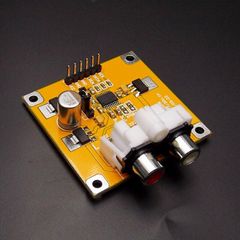
I2S DAC PCM5102 on aliexpress
Search on aliexpress for “Raspberry Pi PCM5102”.
Of cause you can buy HiFiBerry for $35. But aliexpress models four(!) times cheaper.
PCM5102 vs PCM5122
Chinese boards are based on the same IC (PCM5102) as early HiFiBerry (DAC).
New HiFiBerry (DAC+) is based on PCM5122 the main difference in witch is hardware volume control.
If you control volume from your amplifier (the best for sound quality) you do not need the option.
If you want to control volume from your volumio or other music player you can switch on
software volume control. In theory this is bad for sound quality but in practice I do not think you
will see the difference.
| RCA | 3.5mm headphones jack |
 |
 |
Sellers claim that this is Raspberry Pi HAT extensions, but that is not true.
You connect them to HAT socket on Raspberry Pi, but you need some wiring,
you cannot just insert them as HiFiBerry.
Raspberry Pi A/B
On the very early Raspberry Pi version the pins that you need to connect I2S DAC were somethere on the board, but not in any socket. I do not think that you have such an old board so below I describe more modern ones.
Raspbery Pi before “+” version has the pins on 8-pins P5 socket, which is below main
HAT 26-pins socket P1.
In many cases you have to solder P5 for yourself:
video from HiFiBerry.
Take into account that it is supposed to be soldered on back side of the board (in the video above
they solder it on opposite front side).
Because of that odd/even pins in P5 is opposite as in P1.
You can check youself - on P5-1 pin should be 5v, on P5-2
3.3v, and last pins of P5, P5-7 & P5-8 are ground.
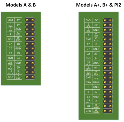
Raspberry Pi A+/B+, Raspberry Pi 2, Raspberry Pi 3, Raspberry Pi Zero
All pins you need for I2S DAC are in main 40-pins HAT socket.
It’s name now J8 and it consists of all 26 pins from old P1, and additional pins.
How to connect I2S DAC to Raspberry Pi
1st DAC version (with fewer pins):
| DAC | Pi A/B | Pi A+/B+, Pi2, Pi3, PiZ | PCM5102 |
|---|---|---|---|
| Vcc (+5v) | P5-1 | J8-2 | |
| +3.3v (not used, just to check youself) | P5-2 | J8-1 | |
| BCK | P5-3 | J8-12 | Audio data bit clock input |
| LRCK(LCK) | P5-4 | J8-35 | Audio data word clock input |
| DATA(DIN) | P5-6 | J8-40 | Audio data input |
| Gnd | P5-7 | J8-39 |
In the board description aliexpress seller wrote that BCK & DATA marked inverse.
But in fact I connected them as marked (BCK is the last pin in DAC’s socket) and everything works fine.
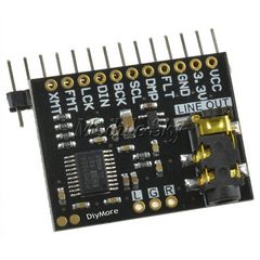
2nd DAC:
Connect additional pins as:
| DAC | Pi A/B | Pi A+/B+, Pi2, Pi3, PiZ | PCM5102 |
|---|---|---|---|
| GND | P1-6 | J8-6 | |
| FLT (gnd) | P1-14 | J8-14 | Filter select : Normal latency (Low) / Low latency (High) |
| DMP (gnd) | P5-8 | J8-20 | ?De-emphasis control for 44.1kHz sampling rate(1): Off (Low) / On (High) |
| SCL | P1-5 | J8-5 | ?System clock input |
| FMT (gnd) | P1-18 | J8-18 | Audio format selection : I2S (Low) / Left justified (High) |
| XMT (3.3v) | P1-1 | J8-1 |
If you want here is all pins description:
RPi Low-level peripherals.
How to setup I2S DAC in Volumio
- Open volumio web-interface - if you have only one volumio in your network you can use http://volumio.local
- Press on cog on the top right corner of volumio window
- Select
Playbackmenu item - Switch on I2S DAC and for I2S driver select
Generic I2S DAC - Press
Apply - Volumio ask to reboot raspberry pi - answer yes